Introduction
Diagnostic Trouble Codes, abbreviated DTCs, are the foundation of automotive diagnostics. In essence, they are 3-byte IDs that represent a specific point of failure or problem in your system (to be fair, SAE-J2012 describes them as 2 bytes, whereas ISO-14229 has them as 3 bytes). If there are failures or issues somewhere in your system, then ECU software can log the failure in the form of setting the trouble code that’s associated with that failure.
The purpose of DTCs is to help repair and diagnose the complex electro-mechanical systems that are in an automobile. When a failure occurs in one of those on-board systems, a unique DTC code becomes activated. Service technicians can read all the DTCs that are active and determine which specific part of a system failed.
Take for example an ECU which interacts with an external analog sensor:
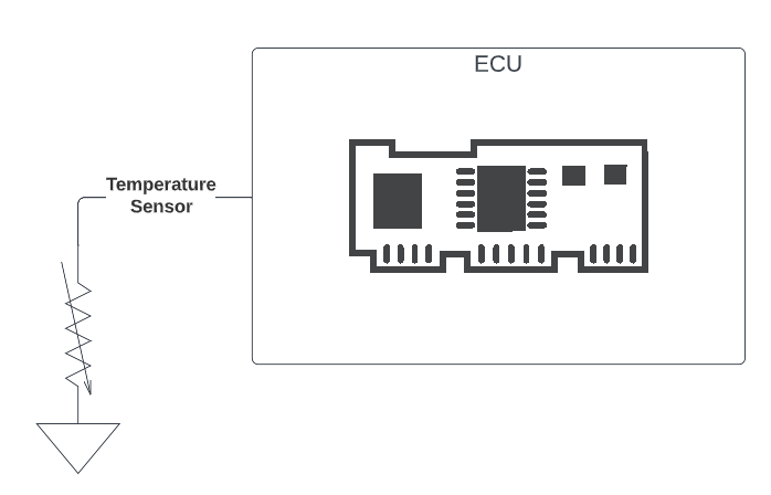
Internally, a well-designed ECU would make sure to interface with the sensor in such a way as to be able to diagnose a connection failure. The system designer would intentionally allocate a DTC to the failure of the sensor connection, and ECU software would periodically diagnose this connection. Finally, if a failure should occur, the ECU software will “set” the DTC that was allocated to this failure mode (we’ll talk about what it means to “set” a DTC shortly).
Though the above example is simple, there’s quite a bit to unpack.
DTC IDs
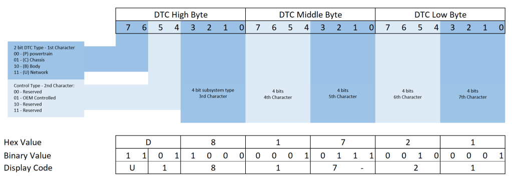
System designers don’t arbitrarily choose 3 bytes to represent a diagnostic failure. Instead, each byte (and in fact, each bit) has a specific meaning that helps identify the type of system that has failed. Broadly, there are 4 categories of DTCs in a vehicle:
- P-Codes (powertrain) – These are DTCs that relate to the torque path of the vehicle. From pedal input all the way down to final drivetrain, any failure points along the way should have an associated DTC that is a P-Code.
- C-Codes (chassis) – These are DTCs that are set by components that aren’t in the torque path but aren’t part of the passenger cabin either. They include systems like steering, suspension, and brakes.
- B-Codes (body) – These DTCs are related to the systems inside and surrounding the passenger cabin, like window motors, cabin heaters, and windshield wipers.
- U-Codes (communication) – Finally, U-Codes are the set of DTCs that deal with communication between different ECUs, and any shared components between them. Failure modes like loss of communication, faulty communication, and implausible signals all come under this category.
In the 3 bytes of a DTC, the upper 2 bits represent the DTC type (P, C, B, or U). The rest of the bits also have a defined meaning:
Tests, Monitors, and Operation Cycles
Before we get into the innards of a DTC, we need to cover some definitions relating to on board diagnostic systems. In an automotive setting, these terms have a very specific meaning, and need to be understood to grasp the concept of diagnostics.
Test
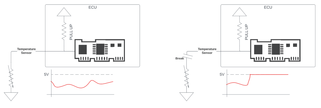
At the core of diagnosing something is performing a test on it to see if its working or not. Some tests are exceedingly simple, others get very complicated. Looking again at our sample ECU and sensor setup, the code that performs the test could be as simple as:
#define SENSOR_HIGH_THRESHOLD       ( 4950 )
#define SAMPLE_WINDOW_SIZE          ( 5 )

/**
 * @brief Performs the out of range diagnostic on the sensor
 * @param [in] sample_mv - fixed point voltage sample in millivolts
 * @return - True if out of range, False otherwise
 */
bool test_sensor_disconnect(uint32_t sample_mv)
{
   /* static variables */
   static int32_t sample_window_position = 0;
   static bool sample_window [ SAMPLE_WINDOW_SIZE ] = { 0U };
   static bool current_state = false;

   /* local variables */
   bool current_sample = false;
   bool out_of_range = true;

   /* check if the current sample is out of range and has failed the diagnostic */
   if (sample_mv > SENSOR_HIGH_THRESHOLD)
   {
      /* this is out of the normal range, and so we say this sample has a failure */
      current_sample = true;
   }

   /* put the sample into the sample window and update
    * position */
   sample_window [ sample_window_position ] =
                 current_sample;
   sample_window_position += 1;
   sample_window_position %= SAMPLE_WINDOW_SIZE;

   /* loop through the sample window, if all samples have failed, report back that the diagnostic has failed, otherwise assume it has passed */
   for (uint32_t index = 0;
        index < SAMPLE_WINDOW_SIZE;
        index += 1)
   {
      if (sample_window [ index ] == false)
      {
          out_of_range = false;
      }
   }

   return out_of_range;
}
The definition of a test, then, is a set of actions that determine whether some part of your system is operating as expected or has failed. The output of a test, then, is a boolean value; pass, or fail. All diagnostics in a system, no matter how complicated or simple, always end in producing this single boolean value. Each one of these pass or fail values are referred to as test samples. Notice that inherent in those samples can be some debouncing behaviour. This doesn’t have to be the case, however.
Monitor
Now that we know what a test is, and what a simple one looks like, we’re ready to proceed to the definition of a diagnostic monitor. Simply put, a monitor is a set of a one or more tests, which together, can diagnose whether a portion of a system is working as intended, or is faulted. There is a 1:1 mapping of DTCs to monitors. Each monitor reports the state of one part of a system to a single DTC code.
Many monitors consist of just one test. For the example above, the monitor could simply be:
/**
 * @brief - The monitor function for this sensor, calls the test, and reports the DTC
 */
void perform_sensor_diagnostic(void)
{
   uint32_t sensor_value_mv = iohwabs_get_sensor_voltage();
   bool sensor_diagnostic_failed = false;

   /* perform all the tests that involve this sensor */
   if (true == test_sensor_disconnect(sensor_value_mv)
   {
      sensor_diagnostic_failed = true;
   }

   /* If the sensor diagnostic failed, report it to the central DTC manager. In this project, the DTC manager takes the hex code of the DTC you wish to report as the first argument, and the failure status as the second argument */
   if (true == sensor_diagnostic_failed)
   {
      report_dtc_status(0xd81721, true);
   }
   else
   {
      report_dtc_status(0xd81721, false);
   }
}
As you can see, a monitor is running the test to diagnose the system (in this case, a sensor). A monitor could have more than one test though. Imagine our same sensor system, but now the DTC associated with that sensor is now more general, and can include multiple points of failure:
/**
 * @brief - The monitor function for this sensor, performs available diagnostics. If the diagnostic failed, report it
 */
void perform_sensor_diagnostic(void)
{
   uint32_t sensor_value_mv = iohwabs_get_sensor_voltage();
   bool sensor_diagnostic_failed = false;

   /* perform all the tests that involve this sensor */
   if (true == test_sensor_disconnect(sensor_value_mv)
   {
      sensor_diagnostic_failed = true;
   }
   if (true == test_sensor_stuck_low(sensor_value_mv)
   {
      sensor_diagnostic_failed = true;
   }
   if (true == test_sensor_stuck_in_range(sensor_value_mv)
   {
      sensor_diagnostic_failed = true;
   }

   /* If the sensor diagnostic failed, report it to the central DTC manager. In this project, the DTC manager takes the hex code of the DTC you wish to report as the first argument, and the failure status as the second argument */
   if (true == sensor_diagnostic_failed)
   {
      report_dtc_status(0xd81721, true);
   }
   else
   {
      report_dtc_status(0xd81721, false);
   }
}
Operation Cycle
The concept of an operation cycle is a bit tricky, and the phrase is somewhat loaded. If you talk to powertrain engineers who work on gas or diesel engines, an operation cycle is a well-defined set of states that the engine goes through. First the engine turns on, then it idles, then it achieves some minimum speed for some minimum time, and then eventually it turns off.
Why not just have operation cycles be key cycles? There’s a lot of regulatory requirements behind what an operation cycle means for a vehicle that has emissions. Basically the spirit of those rules is that an operation cycle has to be long enough and complex enough so that all monitors associated with it are run. Therefore, our definition of an operation cycle is the start and end of the conditions of a vehicle for all the monitors associated with it to run.
A vehicle can have many different subsystems that have their own operation cycles. An example is a hybrid car with an engine and an on-board charger. It doesn’t make sense to associate the DTCs of the on-board charger with the operation cycle of the engine, because the operation of one doesn’t mean the monitors of the other will get exercised. Running the car engine may not necessarily run any of the tests for the on-board charger. Similarly, charging the car with the engine off wouldn’t run any of the tests associated with the engine. Operation cycles are important because of the property that a monitor had to have run at least once in an operation cycle. Knowing that a diagnostic failed doesn’t tell you if it’s a current failure or a past one. Knowing a diagnostic failed in the last operation cycle immediately narrows that down.
DTC Status Byte
Now we get into what it means to “set” a DTC. Let’s bring back our simple system from the introduction:
When the ECU software detects that the sensor has been disconnected, it wants to report that failure. Remember, the end goal of all these DTCs is to help diagnose exactly what went wrong in the system. With that in mind, when a service technician or engineer reads the state of all DTCs on a vehicle, it’s not enough to simply report which ones had a failure. As a technician or engineer trying to diagnose the root cause of the failure, you need more information, such as when did it fail, what was the last time it failed, is it failing every time or is the problem intermittent, etc. Put simply, a simple boolean pass or fail is insufficient for this.
Queue the DTC status byte; though one boolean is insufficient to represent the state of a DTC, it turns out 8 are enough. Together these 8 bits form one status byte, which is descriptive enough to represent a DTC. The 8 booleans are:
| Position | Name | Abbreviation | Description |
| 0 | testFailed | TF | 0 – Last test passed 1 – Last test failed |
| 1 | testFailedThisOperationCycle | TFTOC | 0 – No test has failed since this operation cycle began 1 – At least one test has failed since this operation cycle began |
| 2 | pendingDTC | PDTC | 0 – No test has failed this operation cycle or the last 1 – At least one test failed this operation cycle or the last |
| 3 | confirmedDTC | CDTC | 0 – The test didn’t fail enough to warrant setting a DTC 1 – The test has failed enough times that the DTC is now set |
| 4 | testNotCompleteSinceLastClear | TNCSLC | 0 – At least one diagnostic test has completed since the last time DTCs were cleared 1 – A diagnostic test has not yet run to completion since the last time DTCs were cleared |
| 5 | testFailedSinceLastClear | TFSLC | 0 – A test has not failed since the last time DTCs were cleared 1 – At least one test has failed since the last time DTCs were cleared |
| 6 | testNotCompleteThisOperationCycle | TNCTOC | 0 – At least one test has completed this operation cycle 1 – No test for this DTC has been run since the beginning of this cycle |
| 7 | warningIndicatorRequested | WIR | 0 – No malfunction light is being requested from this DTC 1 – The malfunction light should be illuminated due to this fault |
Each DTC in the system has associated with it one DTC status byte. The DTC code, along with the status byte, provide enough information to a technician or engineer to know what went wrong in a system. Therefore, when we say “set” a DTC, we mean that we should report the fault associated with the system that failed, and that the individual status bits of that DTC should be updated accordingly.
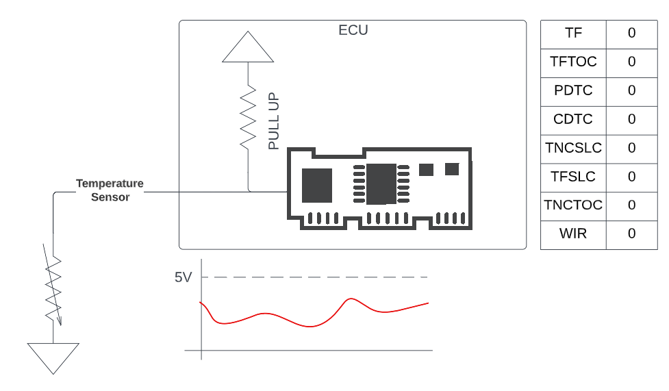
To make this concrete, consider again our simple system with an ECU connected to an external sensor. Let’s assume that there is a DTC to indicate that the sensor has been disconnected from the ECU. At the very beginning, right after you plug in your ECU for the first time (or clear DTCs), the state of the DTC could look like:
Say there is nothing wrong with the sensor – then the tests will begin to pass:
Finally, let’s introduce a fault in the system and see how the DTC status byte changes:
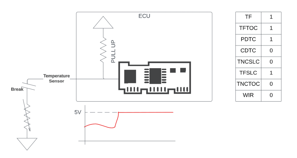
There’s a certain nuance to the PDTC bit and the CDTC bit. Basically, some DTCs take multiple operating cycle of failures before they become “confirmed” (indicating a real problem with the system). In those cases, the pending bit shows that the tests are failing, but haven’t yet failed across enough operation cycles to warrant a warning. The above example system did not set the CDTC bit, and hence we can assume the DTC associated with that sensor is a multi-trip fault. If on the next operating cycle the test fails again, the CDTC bit would get set. We call this kind of DTC a two-trip fault (it takes two trips with a failing test to confirm).
As you can see, with the additional information provided by the status bits, an engineer can quickly determine the state of system. If for example the next time the car comes in for service, or the next time DTCs are read remotely through telematics, they can tell immediately which systems were failing and if they are still failing, providing a powerful, standardized means for diagnosing problems in the car.
Conclusion
We’ve touched on the basics of what DTCs are, and with it a few basic concepts relating to automotive diagnostics, like tests, monitors, and operation cycles. We’ve also seen what’s in a DTC status byte. In a follow up post, we’ll delve more deeply into these concepts and introduce the common software abstraction used to manage all of this: the Diagnostic Event Manager (DEM).

Leave a comment